Telephony Projects at home:
555 PBX Switchboard (Cordboard/Plugboard) and
Step by Step PBX Exchange (Western Electric 9-links, from scratch)
Since the late 19th Century, Central Office telephone exchanges have provided telephone service for local subscribers. Step-by-step “Strowger” switches (automatic exchanges) became widely employed in the 1930s and 1940s. In my hometown, we finally got Rotary Dial (implemented with step-by-step switches) in 1964, having previously had (human) operator-staffed “Number Please” (manual service) switchboard offices.
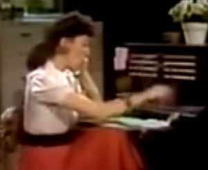
Touchtone (DTMF) started replacing rotary dial in the Bell System in the 1960s. The manual plugboard switchboard was made famous by comedienne Lily Tomlin and her antics as a telephone operator.
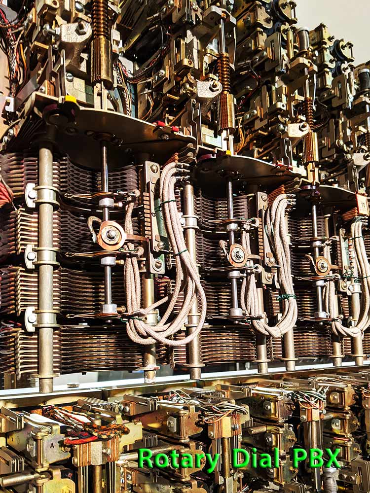
In our rotary dial SxS PBX, we use Western Electric step-by-step switches invented by Almon Strowger, whose funeral home undertaker business was losing clients to a competitor whose telephone-operator wife was redirecting everyone who called for Strowger to her own husband’s business. Motivated to remove the intermediary human operator, he invented the first automatic telephone exchange in 1889 and received its patent in 1891.
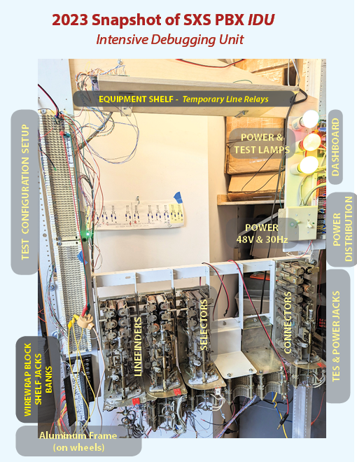
Our home-built PBX in Sterling, MA:

Height designed to fit (roll) through standard doorway.
A flexible/programmable platform for debugging switches:
Why this project? everyone asks
Growing up, I was a telephone nerd, and at age 14 bought my first stepper switch. Without any documentation or instruction, I was able to get it to be somewhat operational, inelegantly mounted hanging at the edge of a stepstool. During high school, in parallel with rebuilding a pipe organ, I bought several rotary stepper switches and added some relays to make a rudimentary 2-phone, 3-digit dial system. Now, upon nearing retirement, the telephone bug has resurfaced, and I started collecting SsS (Strowger step-by-step) switches, and related components to construct a PBX exchange. Ebay was my friend! Blaine welded the steel frame structure and mounted on wheels. It was all learn-as-you-go, not having any documentation at that time.
2026: Now complete and mostly operational, it currently serves as a conversation piece for guests, and eventually will be donated to a museum to demonstrate this technology.
Features of the PBX
- 4-digit stations (subscribers) (7-digit with digit-absorbing: first 3 digits are ignored/absorbed)
- 9 links (simultaneous conversations); 40 switches; 40 stations (line ckts); 4 fuse blocks(one per shelf)
- 200-point line finders
- Additional demonstration technology: AE-style rotary-stepping linefinder (uniselector), and per-station uniselector (line-switch) rotary-stepping hunt for a free first selector
- Dial 8(c*net trunk for internet calls; inward also), 7(Panasonic 612 PBX trunk), 9(outside trunk line(PTSN)), 0(Operator: 555 PBX Switchboard)
- Five ringing cadences (not synchronized), 20 Hz, 30 Hz
- Two intercept recordings (selector, connector levels)
- Dialtone (Imprecise tone: free-running 350 and 440Hz oscillators), busy signal
- Rotary hunt, and level hunt for idle stations (skips busy lines)
- Tone to pulse converters (prior to first selectors)
- Dashboard status lights
- Power : 48, 12, 5 V DC; + & – 110 V DC for payphone coin relay operation for collect and return, and 20 & 30 Hz ringing current from frequency generators
- Aisle pilot lamps (alarm indicator/supervisory status bulbs mounted vertically at the end of the frame- expanded to 10 bulbs)
- 1A2 multi-line key “business” phones
- 3-slot prepay phone trunk and Gray/W.E. 3-slot paystation (payphone/coin box as they’re called)
- Python script (running on a Raspberry Pi) to simulate eight stations randomly dialing (over and over). This serves as a great demonstration for the drama of the relays chattering, as well as a debugging tool (the script keeps history for replaying if needed to recreate a problematic condition)
- 119 reverting selector to have your own line ring (also used for party-lines)
555 PBX Switchboard
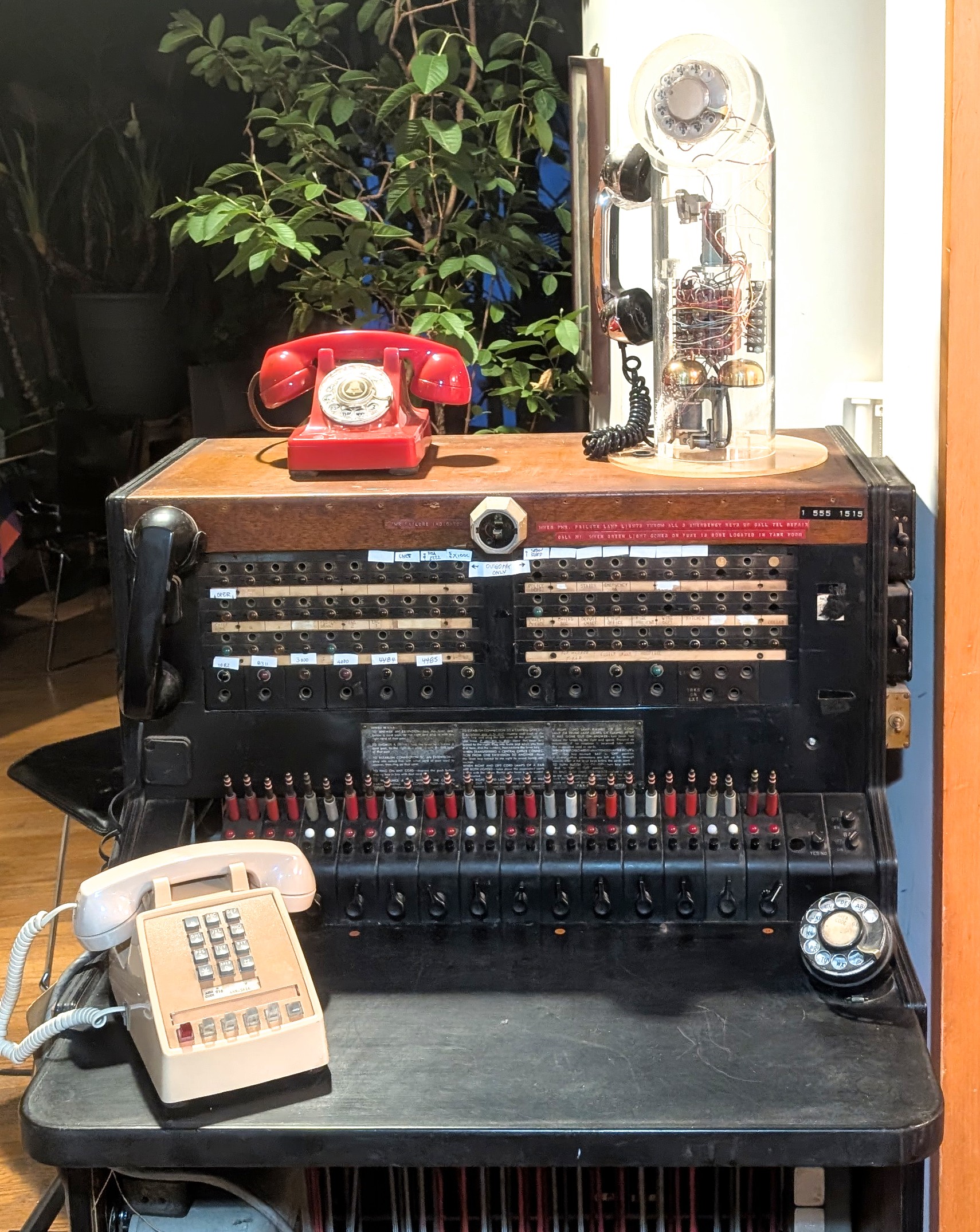
This switchboard was bought at a Sterling yard sale in the 1990s. It was in use at the Leominster Fire Dept Alarm Center ca. 1960-1990 where it served as the PSAP (equivalent of 911 these days) for Fire and Police. It has been restored and expanded to be populated with the full 15 cord circuits and 11 trunk circuits (plus the existing conference circuit).
(above image shown during restoration)
Additionally, trunk circuits were redesigned to have the lamps and buzzer to ring (solid) for the duration (only) of the incoming ringing cycle. The top right station jack and lamp strips were modified to be outgoing (only) trunks and are utilized as PLARs and C*net trunks.
555 Documentation: Technical; Wikipedia; Repository