Engineered for scalability, the Western Electric 555 PBX uses modular cord and trunk circuits to accommodate growing service needs. While this modularity maximizes space efficiency, the resulting component density complicates field repairs. To perform live debugging conveniently without disturbing adjacent circuits, a technician requires a specialized “umbilical extension cable".
In actual practice, technicians would just replace a cord circuit (or tape the emerging plugs as Out Of Service), and thus an extension cable would not have been needed since the module would just be returned for repair. But for collectors and museums, the ability to repair cord circuits becomes critical.
Key obstacles to debugging 555 cord circuits include:
Because the 555 uses proprietary non-standard connectors (whose pins are evocative of Cinch-Jones spade plugs), off-the-shelf connectors do not exist. In fact a separate individual male spade plug does not even exist (to our knowledge).
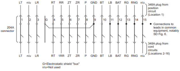
A reliable umbilical can be fabricated using "donor" parts (204A/B spade bank plug strip & 348A socket) from a retired switchboard. Because a self-contained single male spade plug is not possible, we use a subsetted segment of 3 (bussed) spade plugs cut from a donor cord circuit bank plug strip. The resulting umbilical cable is assembled from a female-to-female (348A) cable with a male-to-male 204A/B strip segment, overall yielding a male-to-female cable.
This configuration creates a secure, tethered connection. By removing the cord circuit module from the frame and placing it on the switchboard desk or a nearby lab bench, the technician gains 360-degree access to the components while the module remains electrically integrated into a working board.
Testing Resources:
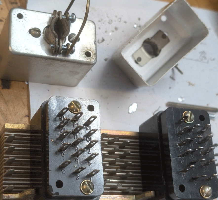
Bare components: 348A socket connectors & 204 spade bank strip segment
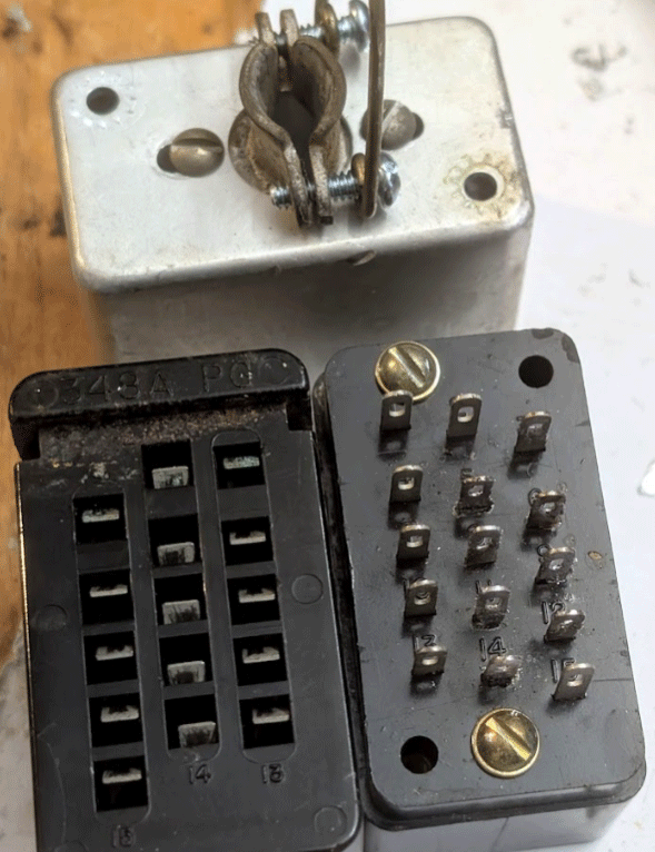
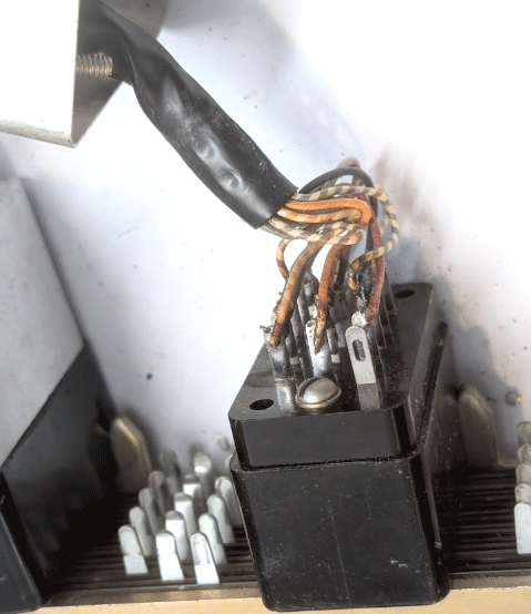
Original 348A socket:
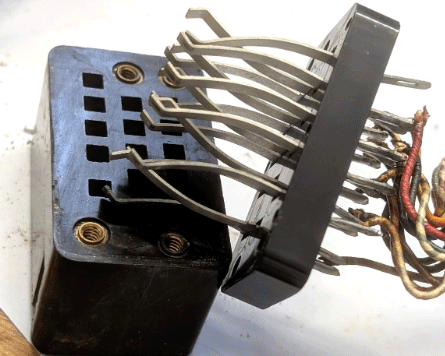
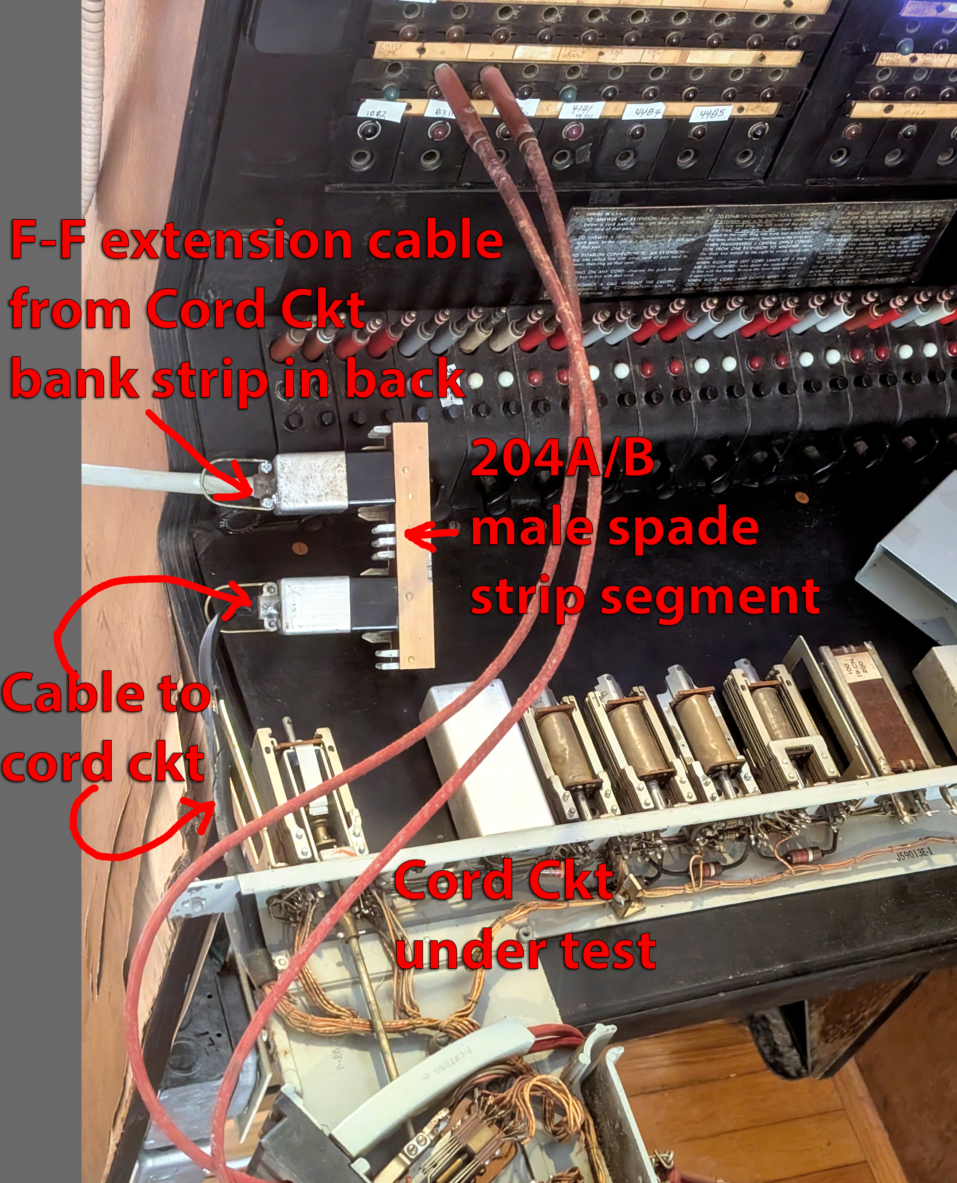
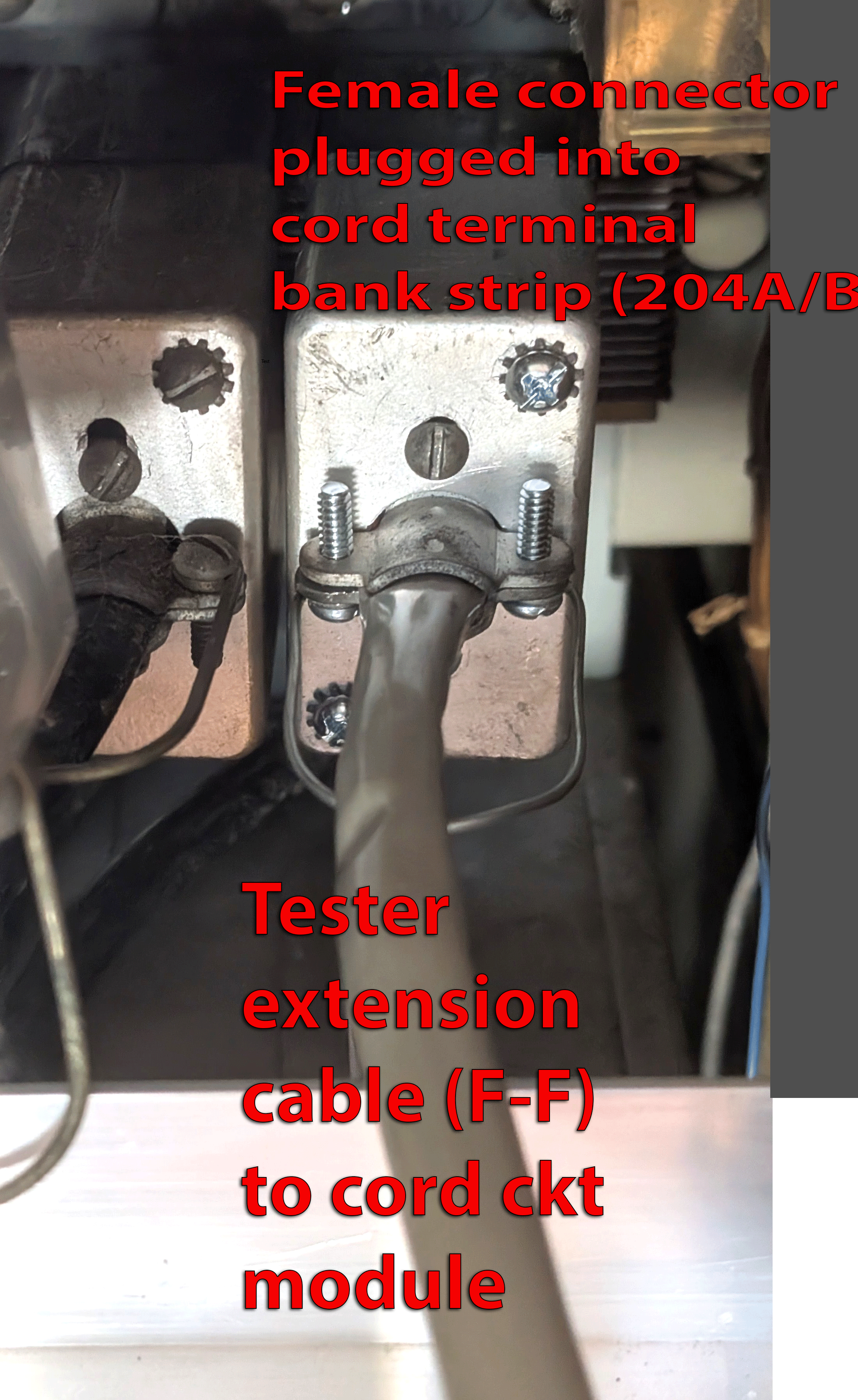
Socket & strip in situ: